Tutorial: Building a Differential Drive Robot
In this tutorial, you will configure a differential drive mobile robot in Blender and export it as an actuable URDF for ROS 2 or Gazebo.
What You Will Learn
How to create and configure Links.
How to connect links with Joints.
How to add a Lidar Sensor.
How to configure Control Interfaces.
How to Validate and Export your robot.
Kinematic Tree
Before we start building, here is the structure of the robot we are going to create:
        graph TD
    base_link[base_link] -->|continuous| left_wheel[left_wheel]
    base_link -->|continuous| right_wheel[right_wheel]
    base_link -->|fixed| lidar_link[lidar_link]
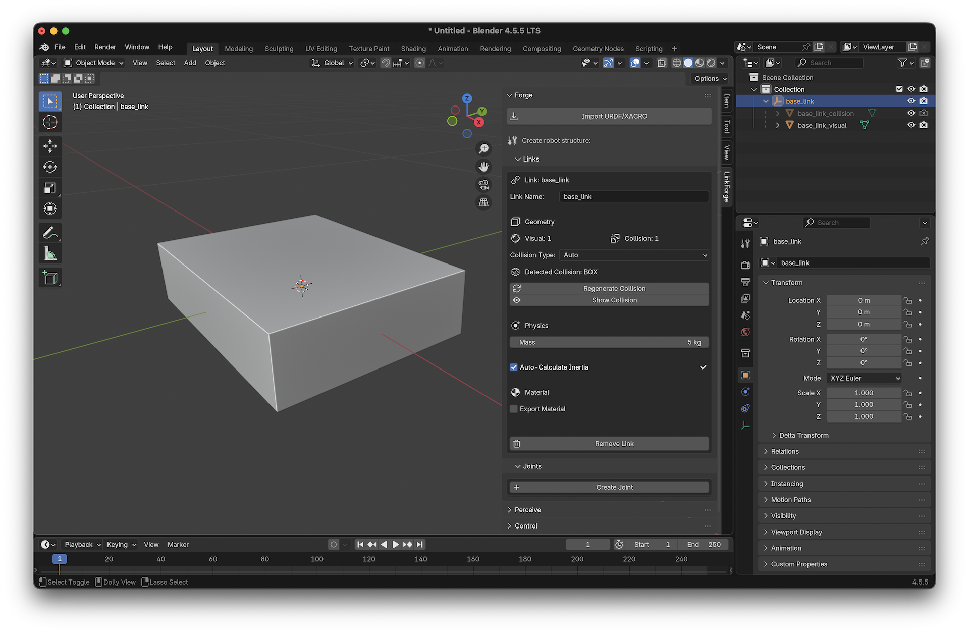
Step 1: Create the Base Link
Add a Mesh: In Blender, press
Shift + Aand select Mesh > Cube.Scale the Base: Set the dimensions to roughly
0.4m x 0.3m x 0.1m.Forge the Link:
Open the Links panel in the LinkForge sidebar (
Nkey).With the cube selected, click Create Link from Mesh.
Name it
base_link.Set Mass to
5.0kg.Enable Auto-Calculate Inertia (LinkForge will automatically generate the inertia tensor for the box).
Generate Collision: Click Generate Collision. LinkForge will create an optimized bounding box for the cube.
Tip
Always keep LinkForge’s Auto-Calculate Inertia checkbox enabled rather than entering values manually. It ensures the physical consistency required by simulation engines like Gazebo.
Step 2: Create the Wheels
Add a Cylinder:
Shift + A> Mesh > Cylinder.Dimensions: Set Radius to
0.1mand Depth to0.05m.Rotate: Rotate it 90 degrees on the X-axis so it looks like a wheel.
Duplicate: Press
Shift + Dand move the new cylinder to the other side. You now have two generic cylinder meshes.
Forge the Left Wheel
Select the first cylinder.
Click Create Link from Mesh.
Name it
left_wheel.Set Mass to
0.5kg.Generate Collision: Click Generate Collision.
Forge the Right Wheel
Select the second cylinder.
Click Create Link from Mesh.
Name it
right_wheel.Set Mass to
0.5kg.Generate Collision: Click Generate Collision.
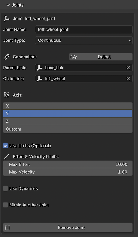
Step 3: Connect with Joints
Connect Left Wheel:
Select
left_wheel.In the LinkForge sidebar, go to the Joints panel and click Create Joint.
Type: Select
continuous(wheels don’t have limits).Parent: Select
base_link.Axis: Set to
(0, 1, 0)if your wheel rotates around the Y-axis.
Connect Right Wheel:
Repeat the process for
right_wheel, connecting it tobase_link.
Step 4: Add a Lidar Sensor
Create Lidar Mesh: Add a small cylinder on top of the base.
Create Link from Mesh: Call it
lidar_link.Create Fixed Joint: Connect
lidar_linktobase_linkusing afixedjoint type.Attach Sensor:
Go to the Perceive panel in the LinkForge sidebar.
With
lidar_linkselected, click Create Sensor.Select Type:
LIDAR(LinkForge exports this asgpu_lidarfor modern Gazebo).Set Update Rate to
30Hz.
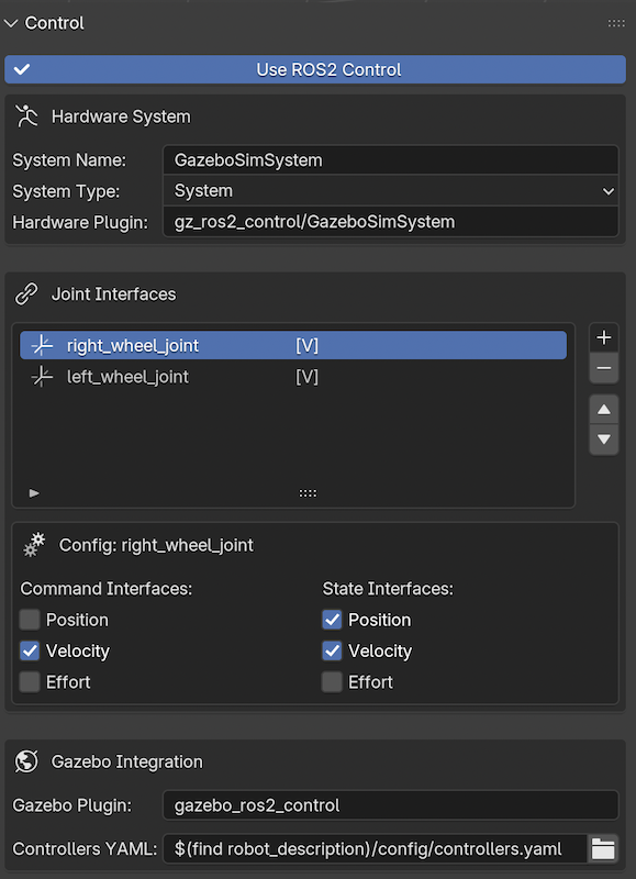
Step 5: Configure Control
To make our robot actuable in ROS 2 or Gazebo, we need to add standard interfaces (Velocity) to the wheels using the ros2_control system.
Open Control Dashboard:
Go to the Control panel in the LinkForge sidebar.
Check Use ROS2 Control.
This enables the centralized dashboard.
Add Interfaces:
Click the Add (+) button next to the “Joint Interfaces” list.
Select
left_wheel_joint.Click Add (+) again and select
right_wheel_joint.
Configure Velocity Control:
Select
left_wheel_jointin the list.Check Velocity under Command Interfaces.
Check Position and Velocity under State Interfaces (standard for feedback).
Repeat this configuration for
right_wheel_joint.
Step 6: Validate and Export
Validate: In the Validate & Export panel, click Validate Robot.
LinkForge will check if all links are connected, physics data is valid, and control interfaces are set.
Warning
Exporting without validation may result in a URDF that causes simulators to crash or behave erratically. Fix all red markers before proceeding.
Export:
Go to the Validate & Export panel.
Select Format:
URDF.Click Export URDF/XACRO and choose a location.
Success!
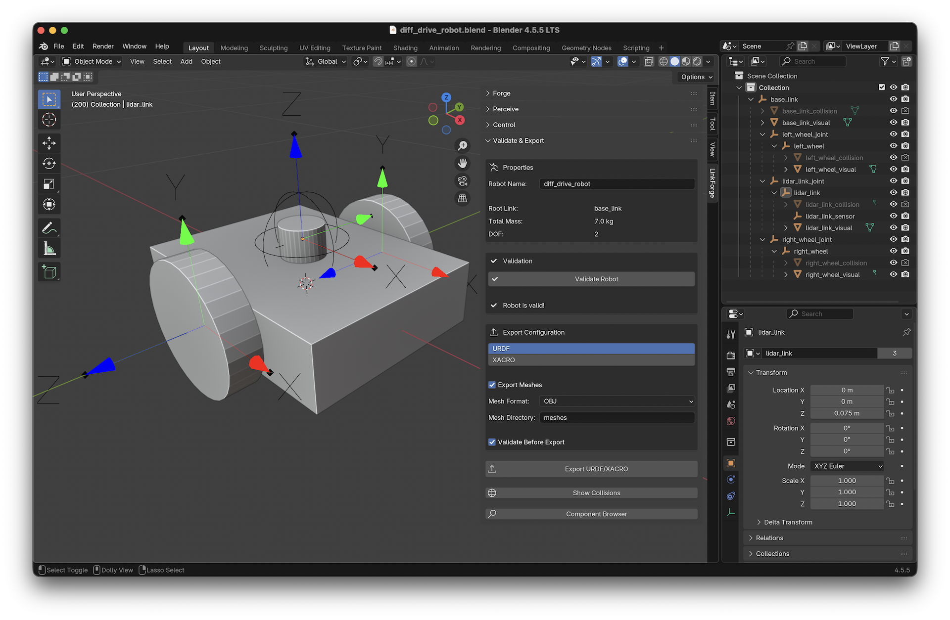
You now have a production-ready, actuable URDF file. You can now load this file into Gazebo or use it with ROS 2 and the diff_drive_controller to drive your robot!
Sample URDF Output
If you followed the steps correctly, your exported URDF should look similar to the following. Note the clean ros2_control block and absence of legacy <transmission> tags.
Click to view diff_drive_robot.urdf
<robot name="diff_drive_robot">
  <!-- Links -->
  <link name="base_link">
    <visual>
      <geometry>
        <box size="0.4 0.3 0.1" />
      </geometry>
    </visual>
    <collision>
      <geometry>
        <box size="0.4 0.3 0.1" />
      </geometry>
    </collision>
    <inertial>
      <mass value="5" />
      <inertia ixx="0.041667" ixy="0" ixz="0" iyy="0.070833" iyz="0" izz="0.104167" />
    </inertial>
  </link>
  <link name="left_wheel">
    <visual>
      <geometry>
        <cylinder radius="0.1" length="0.05" />
      </geometry>
    </visual>
    <collision>
      <geometry>
        <cylinder radius="0.1" length="0.05" />
      </geometry>
    </collision>
    <inertial>
      <mass value="0.5" />
      <inertia ixx="0.001354" ixy="0" ixz="0" iyy="0.001354" iyz="0" izz="0.0025" />
    </inertial>
  </link>
  <link name="right_wheel">
    <visual>
      <geometry>
        <cylinder radius="0.1" length="0.05" />
      </geometry>
    </visual>
    <collision>
      <geometry>
        <cylinder radius="0.1" length="0.05" />
      </geometry>
    </collision>
    <inertial>
      <mass value="0.5" />
      <inertia ixx="0.001354" ixy="0" ixz="0" iyy="0.001354" iyz="0" izz="0.0025" />
    </inertial>
  </link>
  <link name="lidar_link">
    <visual>
      <geometry>
        <cylinder radius="0.03174" length="0.037866" />
      </geometry>
    </visual>
    <inertial>
      <mass value="1" />
      <inertia ixx="0.000371" ixy="0" ixz="0" iyy="0.000371" iyz="0" izz="0.000504" />
    </inertial>
  </link>
  <!-- Joints -->
  <joint name="left_wheel_joint" type="continuous">
    <origin xyz="0 0.175 0" rpy="1.570796 0 0" />
    <parent link="base_link" />
    <child link="left_wheel" />
    <axis xyz="0 1 0" />
    <limit effort="10" velocity="1" />
  </joint>
  <joint name="right_wheel_joint" type="continuous">
    <origin xyz="0 -0.175 0" rpy="1.570796 0 0" />
    <parent link="base_link" />
    <child link="right_wheel" />
    <axis xyz="0 1 0" />
    <limit effort="10" velocity="1" />
  </joint>
  <joint name="lidar_link_joint" type="fixed">
    <origin xyz="0 0 0.064282" rpy="0 0 0" />
    <parent link="base_link" />
    <child link="lidar_link" />
  </joint>
  <!-- ROS2 Control -->
  <ros2_control name="GazeboSimSystem" type="system">
    <hardware>
      <plugin>gz_ros2_control/GazeboSimSystem</plugin>
    </hardware>
    <joint name="right_wheel_joint">
      <command_interface name="velocity" />
      <state_interface name="position" />
      <state_interface name="velocity" />
    </joint>
    <joint name="left_wheel_joint">
      <command_interface name="velocity" />
      <state_interface name="position" />
      <state_interface name="velocity" />
    </joint>
  </ros2_control>
  <!-- Gazebo -->
  <gazebo>
    <plugin name="gazebo_ros2_control" filename="libgz_ros2_control-system.so">
      <parameters>$(find robot_description)/config/controllers.yaml</parameters>
    </plugin>
  </gazebo>
  <!-- Sensors -->
  <gazebo reference="lidar_link">
    <sensor name="lidar_link_sensor" type="gpu_lidar">
      <always_on>true</always_on>
      <update_rate>30</update_rate>
      <visualize>false</visualize>
      <topic>/lidar_link_sensor</topic>
      <ray>
        <scan>
          <horizontal>
            <samples>640</samples>
            <resolution>1</resolution>
            <min_angle>-1.570796</min_angle>
            <max_angle>1.570796</max_angle>
          </horizontal>
        </scan>
        <range>
          <min>0.1</min>
          <max>10</max>
          <resolution>0.01</resolution>
        </range>
      </ray>
    </sensor>
  </gazebo>
</robot>